High Enthalpy and Propulsion Laboratory
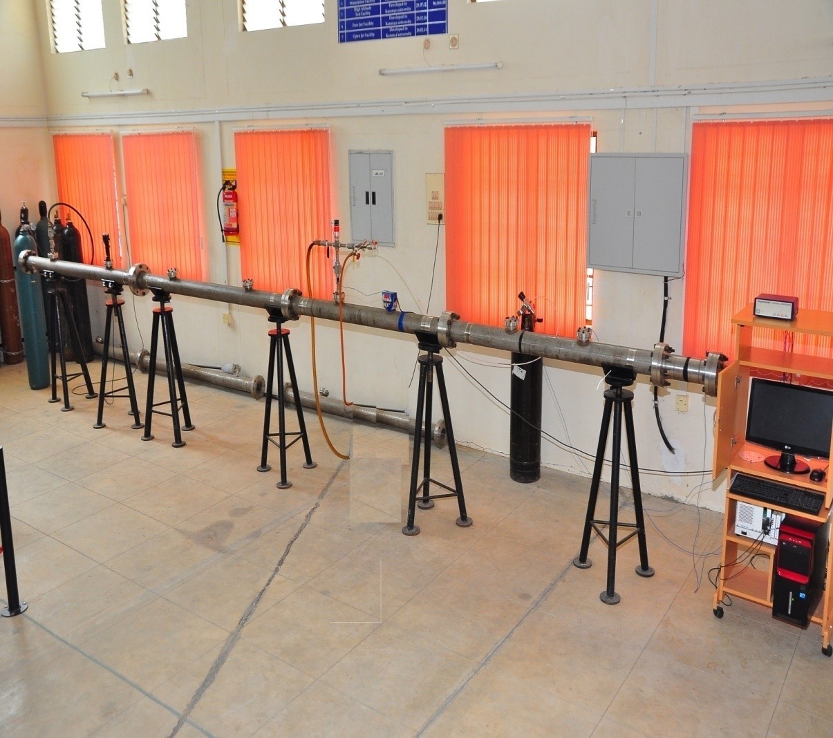
Shock tube Facility
The shock tube is an instrument used to replicate and direct blast waves at a sensor or a model in order to simulate actual explosions and their effects, usually on a smaller scale. Shock tubes are also used to investigate compressible flow phenomena and gas phase combustion reactions.
Specifications
- ID 80 mm, OD 116 mm
- driver section length: 2 m
- driven section length : 1.5 m to 11.5 m.
- Data Acquisition system
- NI-based PXI -1031 chassis
- Signal Conditioner 482 series PCB piezotronics
- GUI with Lab-view
- Sensors/Detectors
- High frequency PCB pressure transducer
- CH* emission measurement with the help of photo diode
- Pressure transducers
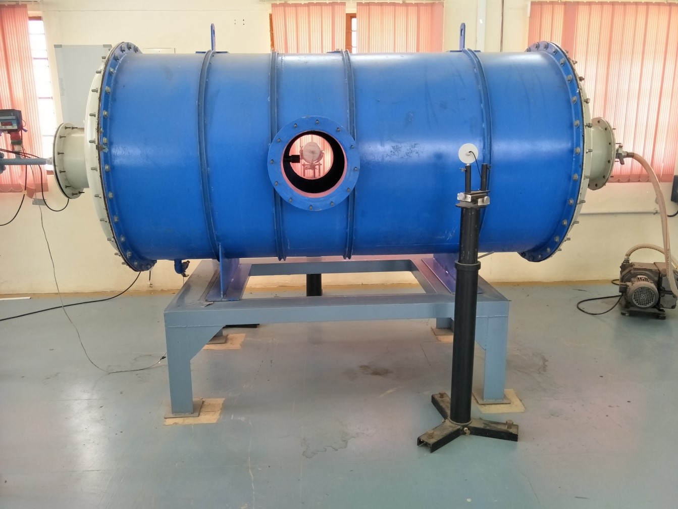
High Altitude test facility
Sub-sonic wind tunnel
The high altitude test facility consists of a high pressure compressor, vacuum pump and a vacuum tank. The central part of the HAT is the vacuum tank. It is evacuated by the vacuum pump to provide the required vacuum. Inside this tank the nozzle and free jet region are located. It is equipped with two oppositely located windows in order to offer a path for the light beams of the Schlieren system.
Specifications
- Tank is 1 m dia and 2 m long
- Pressure range: 0.001 bar to 20 bar
- Velocities: Mach 1.5 to 4
Nozzle shock wave

Kinetic Heating Simulation Facility

Kinetic Heating Simulation facility is an experimental scheme which simulates the convective heating experienced by an aerodynamic body (in ascend heating) by dynamically heating the test article by radiation panels. The process is achieved through a closed loop heating system.
Applications
- Design validation of Thermal protection system for aerodynamic heating of rockets, heat shields etc.
- Performance evaluation of thermal paints.
- New light weight Material development which can withstand high heat flux
Water Tunnel

Specifications
- Test section 0.18*0.25*0.46m (W*H*L)
- Flow velocity 0.05-0.13m/s
- Capacity 300 liters
- Turbulence intensity <0.5% RMS
Applications
- Flow visualization of models in underwater applications.
- Tracing of stream line, streak line and path line flow under various Reynolds Numbers.
- Effect of high Reynolds flow over the model.
Injector Calibration facility
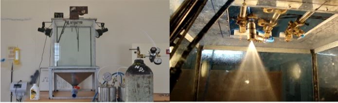
Specifications
- Flow rates- 0.01 to 1 kg/sec
- Flow rates- 0.01 to 1 kg/sec
- Max overhead pressure – 30 bar
Measurements
- Pressure drop vs. volumetric flow
- Temperature measurement of the propellants
- Uniformity of droplets by high speed photography
- Spray angle
Applications
- Spray characterization of various types of injectors like shower head, coaxial, swirl type and impingement injector.
Rocket Engine Test Rig
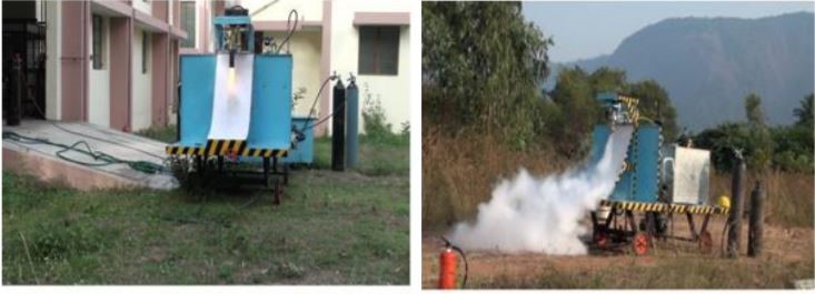
- Rocket engine test stand facility is used to test a static rocket engine for various operating condition. The propellant used are Lox- Kerosene or Lox- H2 gas. The maximum design thrust is 500 kgf for duration of 20 sec.
Instrumentation / Measurements
- Thrust
- Chamber pressure
- Ignition delay
- Thrust chamber skin temperature
- Propellant flow rates
- Propellant temperature
Jet Engine
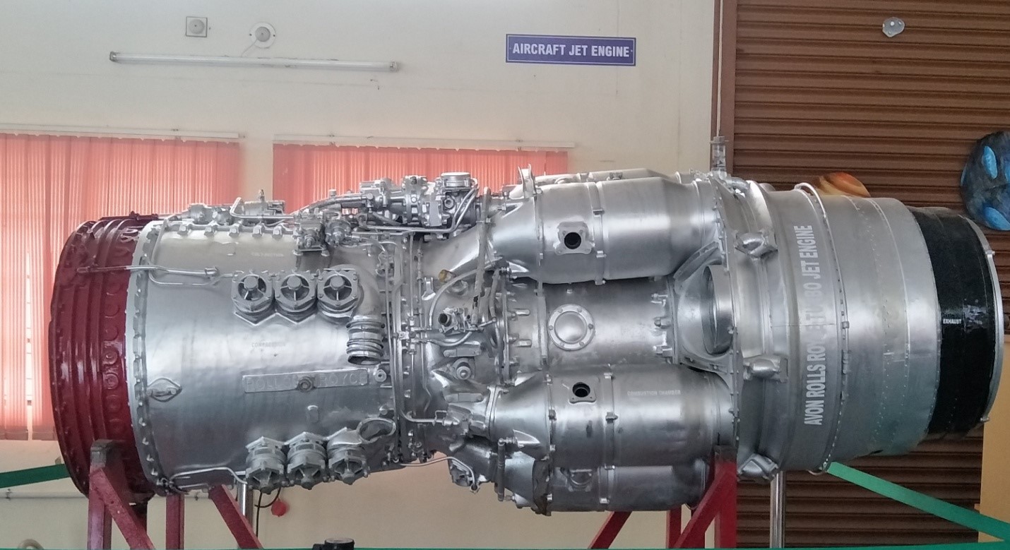
The Rolls-Royce Avon was the first axial flow jet engine designed and produced by Rolls-Royce. Introduced in 1950, the engine went on to become one of their most successful post-World War II engine designs. It was used in a wide variety of aircraft, both military and civilian, as well as versions for stationary and maritime power.
General characteristics
- Type: Turbojet
- Length
- Diameter: 760 mm
- Dry weight: 2,890 lb (1,310 kg)
Components
- Compressor: axial flow
- Combustors: cannular
- Turbine: two-stage axial flow
- Fuel type: kerosene based