SHOCK TUBE FACILITY
The shock tube is an instrument used to replicate and direct blast waves at a sensor or a model in order to simulate actual explosions and their effects, usually on a smaller scale. Shock tubes are also used to investigate compressible flow phenomena and gas phase combustion reactions.
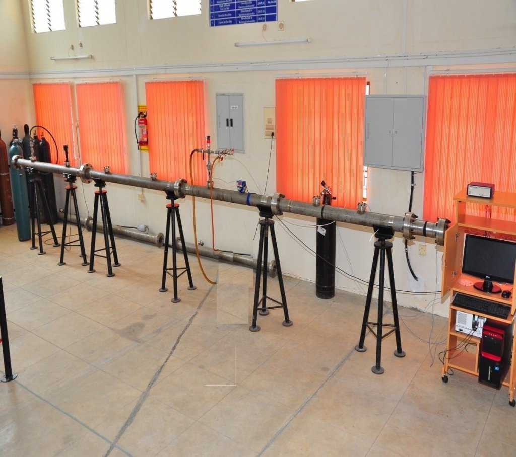
Shock tube Facility
Specifications:
- ID 80 mm, OD 116 mm
- Driver section length: 2 m
- Driven section length: 1.5 m to 11.5 m.
- Contraction ratio 6:1
- Data Acquisition system
- NI-based PXI -1031 chassis
- Signal Conditioner 482 series PCB piezotronics
- GUI with Lab-view
- Sensors/Detectors
- High frequency PCB pressure transducer
- CH* emission measurement with the help of photo diode
- Pressure transducers
HIGH ALTITUDE TEST FACILITY
The high altitude test facility consists of a high pressure compressor, vacuum pump and a vacuum tank. The central part of the HAT is the vacuum tank. It is evacuated by the vacuum pump to provide the required vacuum. Inside this tank the nozzle and free jet region are located. It is equipped with two oppositely located windows in order to offer a path for the light beams of the Schlieren system.
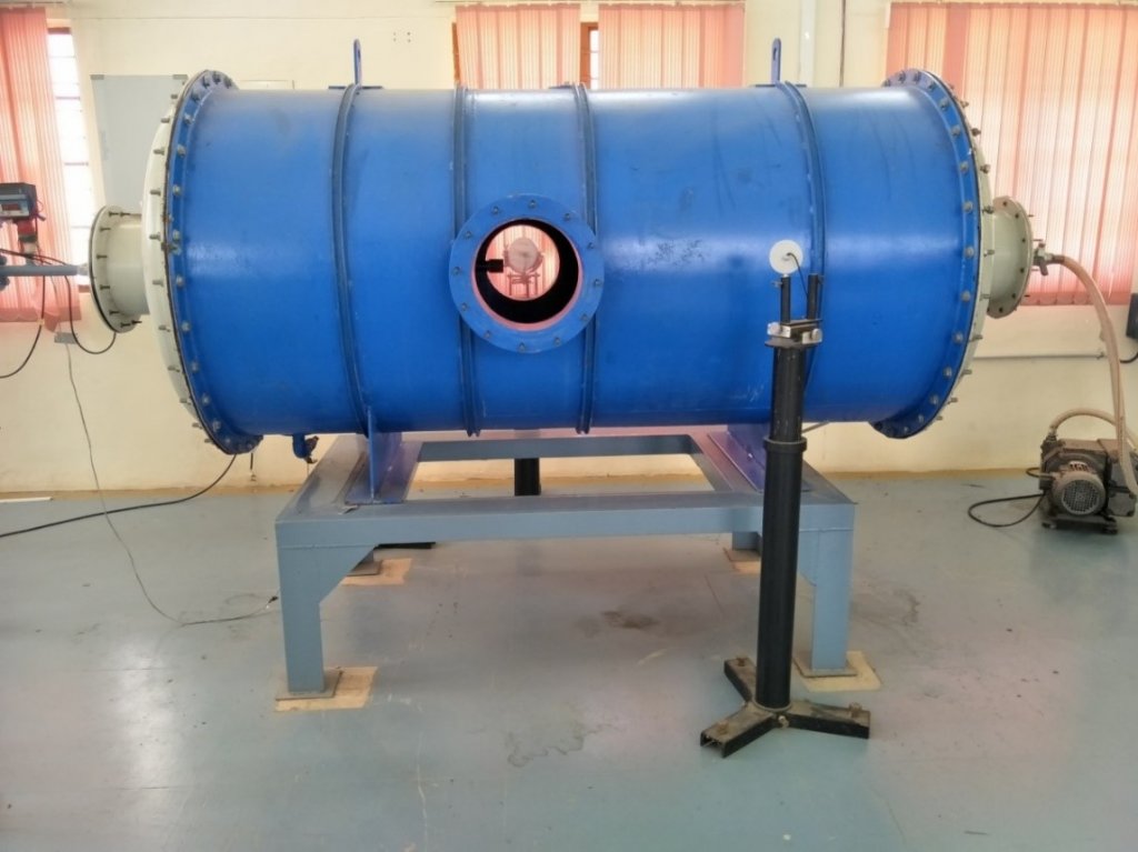
High Altitude Test Facility
Specifications:
- Tank is 1 m dia and 2 m long
- Pressure range: 0.001 bar to 20 bar
- Velocities: Mach 1.5 to 4
KINETIC HEATING SIMULATION FACILITY
Kinetic Heating Simulation facility is an experimental scheme which simulates the convective heating experienced by an aerodynamic body (in ascend heating) by dynamically heating the test article by radiation panels. The process is achieved through a closed loop heating system.
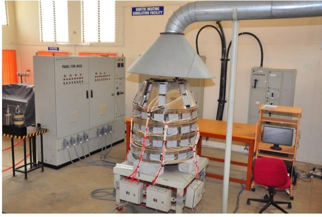
Kinetic Heating Simulation facility
Applications:
- Design validation of Thermal protection system for aerodynamic heating of rockets, heat shields etc.
- Performance evaluation of thermal paints
- New light weight Material development which can withstand high heat flux
WATER TUNNEL
Applications:
- Flow visualization of models in underwater applications.
- Tracing of stream line, streak line and path line flow under various Reynolds Numbers.
- Effect of high Reynolds flow over the model.
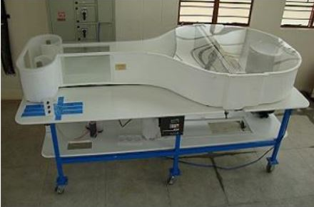
Water Tunnel
Specifications:
- Test section 0.18*0.25*0.46m (W*H*L)
- Flow velocity 0.05-0.13m/s
- Capacity 300 liters
- Turbulence intensity <0.5% RMS
INJECTOR CALIBRATION FACILITY
Applications:
Injector Calibration facility
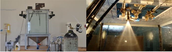
Injector Calibration Facility
Measurements:
- Flow rates- 0.01 to 1 kg/sec
- Duration – 10-30 sec
- Max overhead pressure – 30 bar
Specifications:
Measurements:
- Pressure drop vs. Volumetric flow
- Temperature measurement of the propellants
- Uniformity of droplets by high speed photography
- Spray angle
ROCKET ENGINE TEST RIG
Rocket engine test stand facility is used to test a static rocket engine for various operating condition. The propellant used are Lox- Kerosene or Lox- H2 gas. The maximum design thrust is 500 kgf for duration of 20 sec.
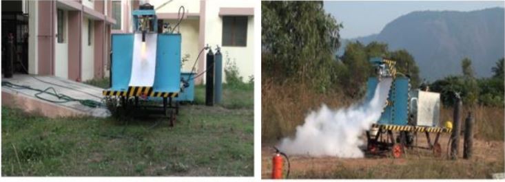
Rocket Engine Test Rig
Measurements:
- Thrust
- Chamber pressure
- Ignition delay
- Thrust chamber skin temperature
- Propellant flow rates
- Propellant temperature
JET ENGINE
The Rolls-Royce Avon was the first axial flow jet engine designed and produced by Rolls-Royce. Introduced in 1950, the engine went on to become one of their most successful post-World War II engine designs. It was used in a wide variety of aircraft, both military and civilian, as well as versions for stationary and maritime power.
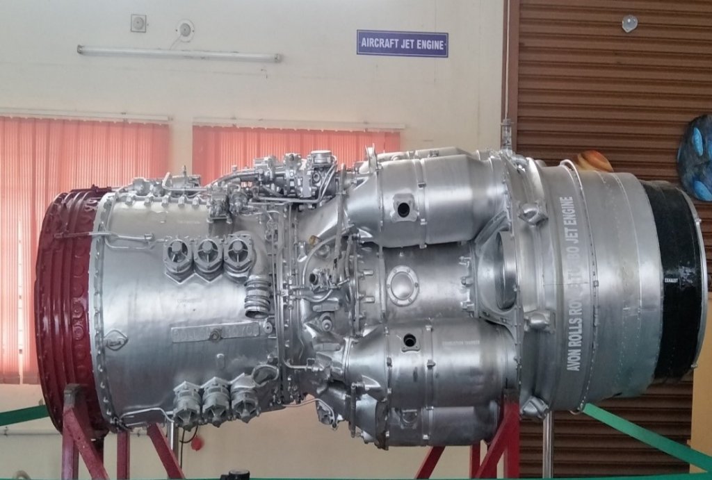
Jet Engine
General characteristics:
- Type: Turbojet
- Length: 2602 mm
- Diameter: 760 mm
- Dry weight: 2,890 lb (1,310 kg)
Components:
- Compressor: axial flow
- Combustors: cannular
- Turbine: two-stage axial flow
- Fuel type: kerosene based
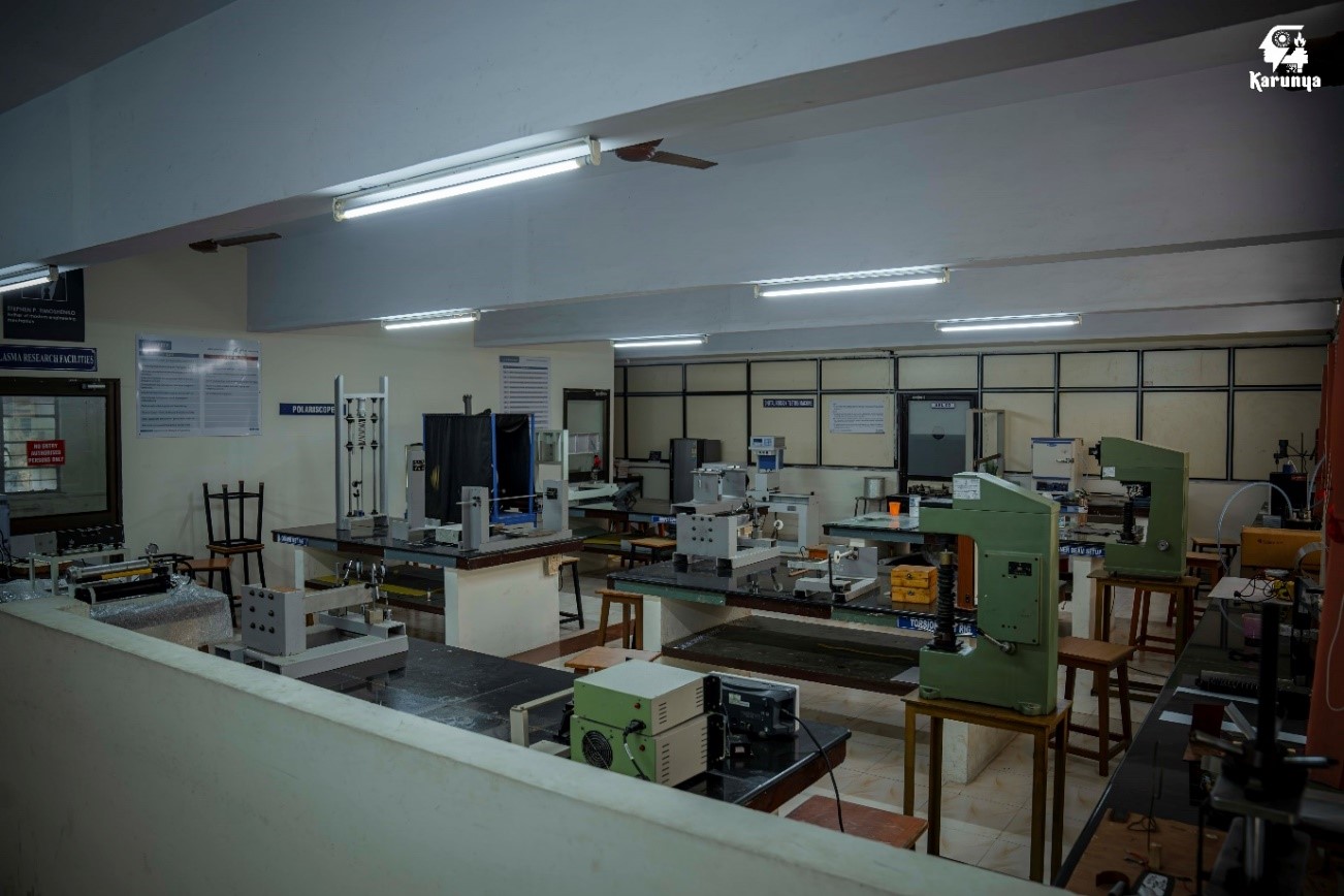
AIRCRAFT STRUCTURES LABORATORY
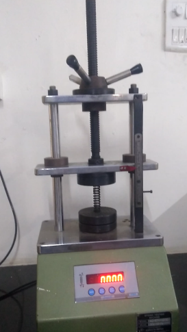
UNIVERSAL TESTING MACHINE (UTM)
UTM is used to determine the tensile strength of a given specimen by generating stress verses strain graphs. Mechanical properties such as modulus of elasticity, yield strength and ultimate strength can be determined for the given material.
Capacity: 20 kN
.jpg)
Universal Testing Machine(UTM)
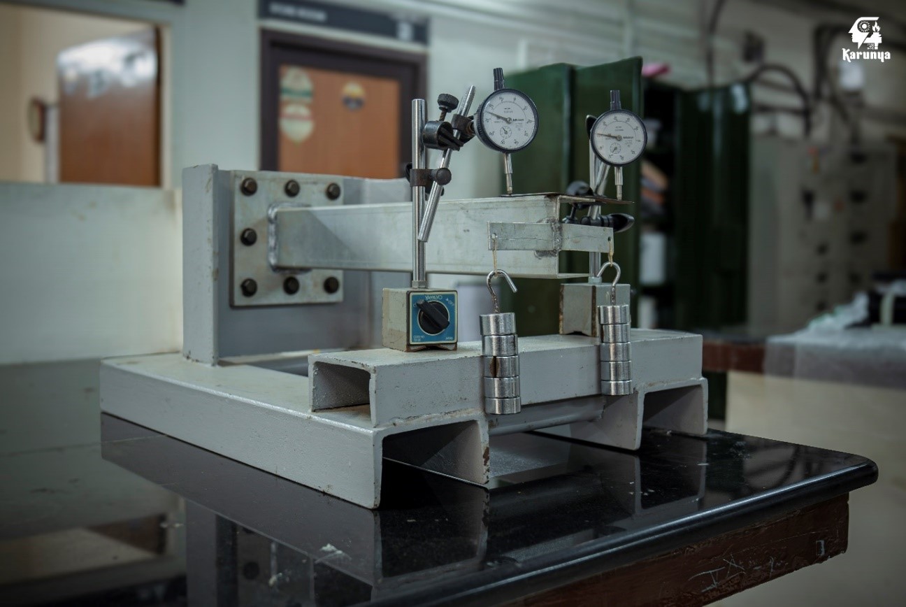
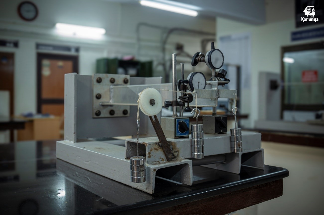
SHEAR CENTRE OF OPEN SECTIONS
Shear center is a point on the cross of the beam and the shear force passes through this point which causes the beam to bend without twisting. If the resultant of the internal shear force system and the applied shear force at any section do not coincide, a torque is developed and the section undergoes a twist. For the section not to twist, the applied shear force must pass through the shear center which is the centroid of the internal shear force system. The experimental setup is used to determine the shear center of ‘C’ section beam.
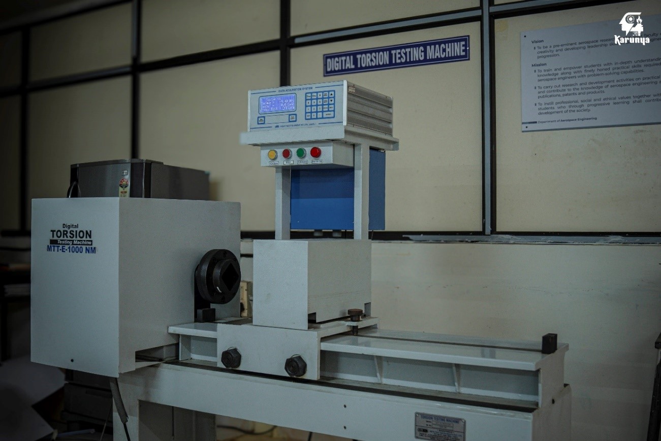
TORSION OF A THIN WALLED TUBE AND SOLID SHAFT
Tubes and shafts are among the most commonly used structures in engineering and subjected to torque. The objective of this experiment is to determine the shear modulus of the material by measuring the angle of twist due to the torque applied on the tube/ Shaft.
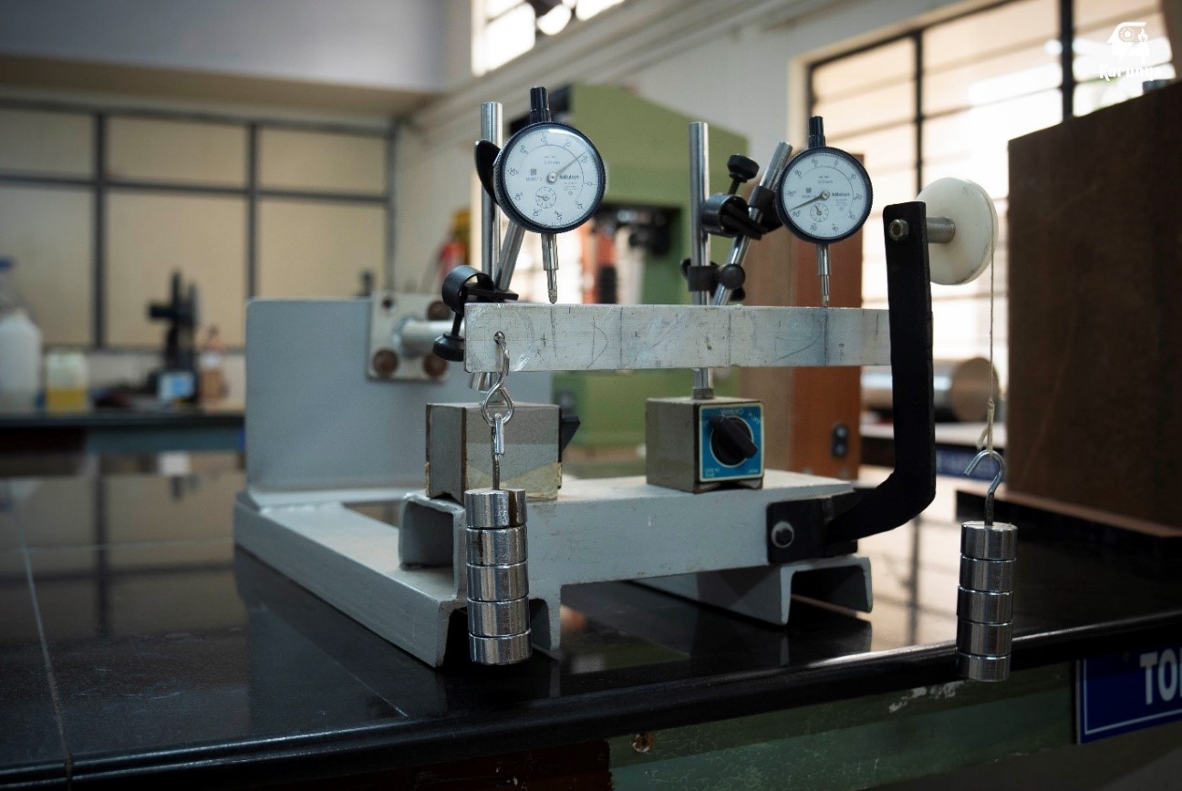
UNSYMMETRICAL BENDING OF BEAM
The well-known flexure formula is based on elementary theory of bending of beams and it assumes that the load is always applied through one of the principal axes of the section. Though the applied load passes through shear centre of the section, the plane of bending and the plane of loading need not necessarily be the same unless the load passes along the principal axes. Therefore knowledge of the location of the principal axes is required. The experimental is used to determine the principal axes.
COMPRESSION TEST ON COLUMN, CRITICAL BUCKLING LOADS – SOUTHWELL PLOT
The need for materials with high strength to weight ratio in aircraft design has resulted in the use of slender structural components that fail more often by instability (buckling) than by excessive stress. The simplest example of such a structural component is slender column. The Southwell plot is a graphical method of determining experimentally a columns critical load. The technique can be used as a non-destructive testing of any structural elements that may fail by buckling.
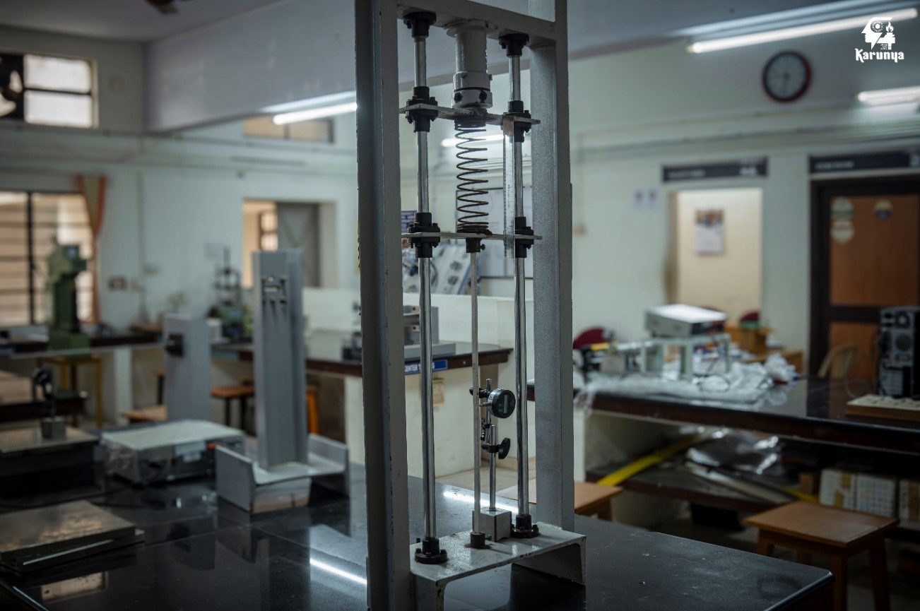
SPRING TESTING SETUP – STIFFNESS OF THE SPRING
Stiffness is a measure of ability of the material to resist the deformation in response to an applied force. Generally spring stiffness is the force required to cause unit deflection. The spring testing setup is used to determine the stiffness of the spring.
Experimental setup to determine spring stiffness
FLIGHT SIMULATOR FACILITY
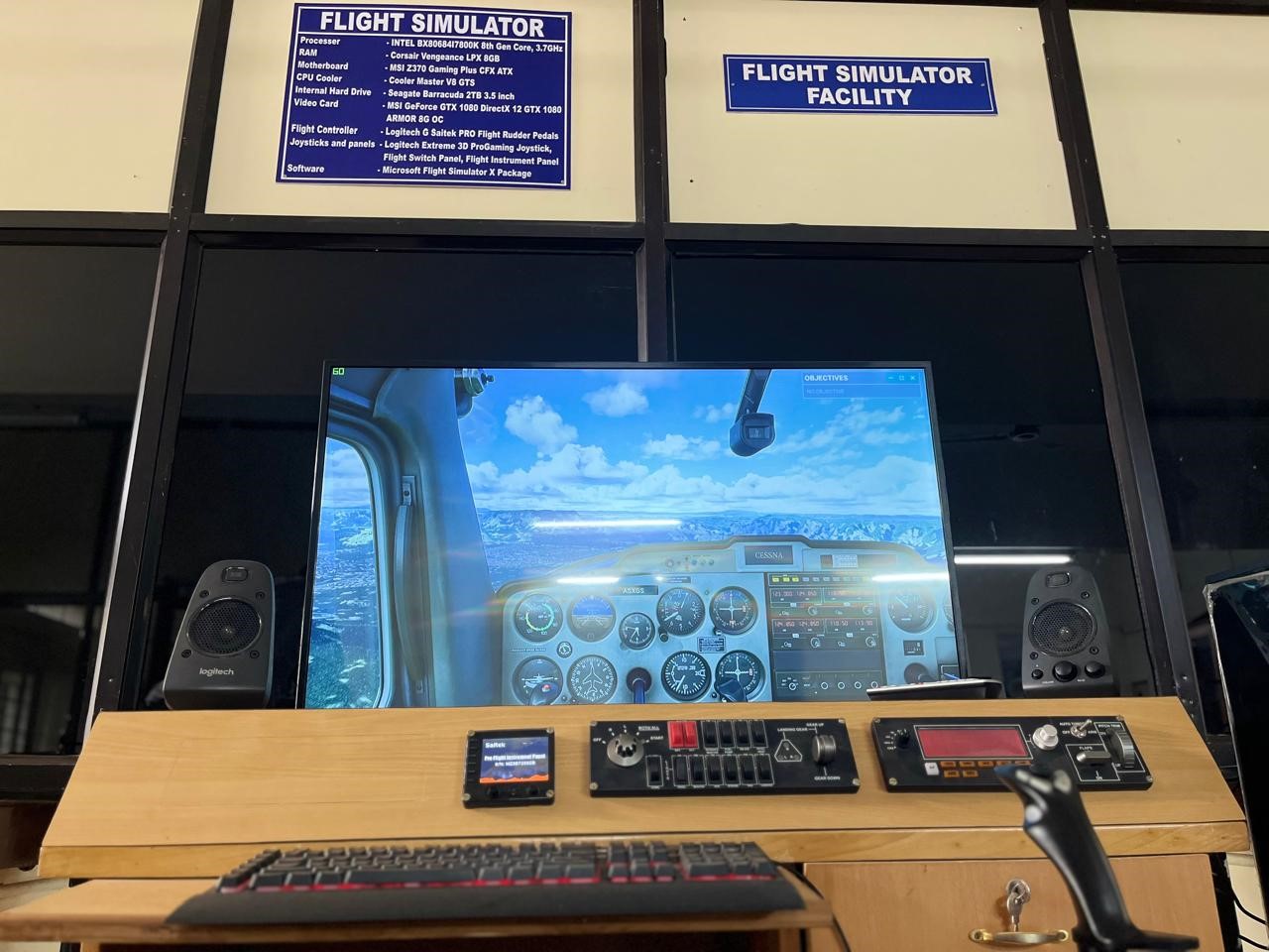
Flight Simulator
PID CONTROLLER
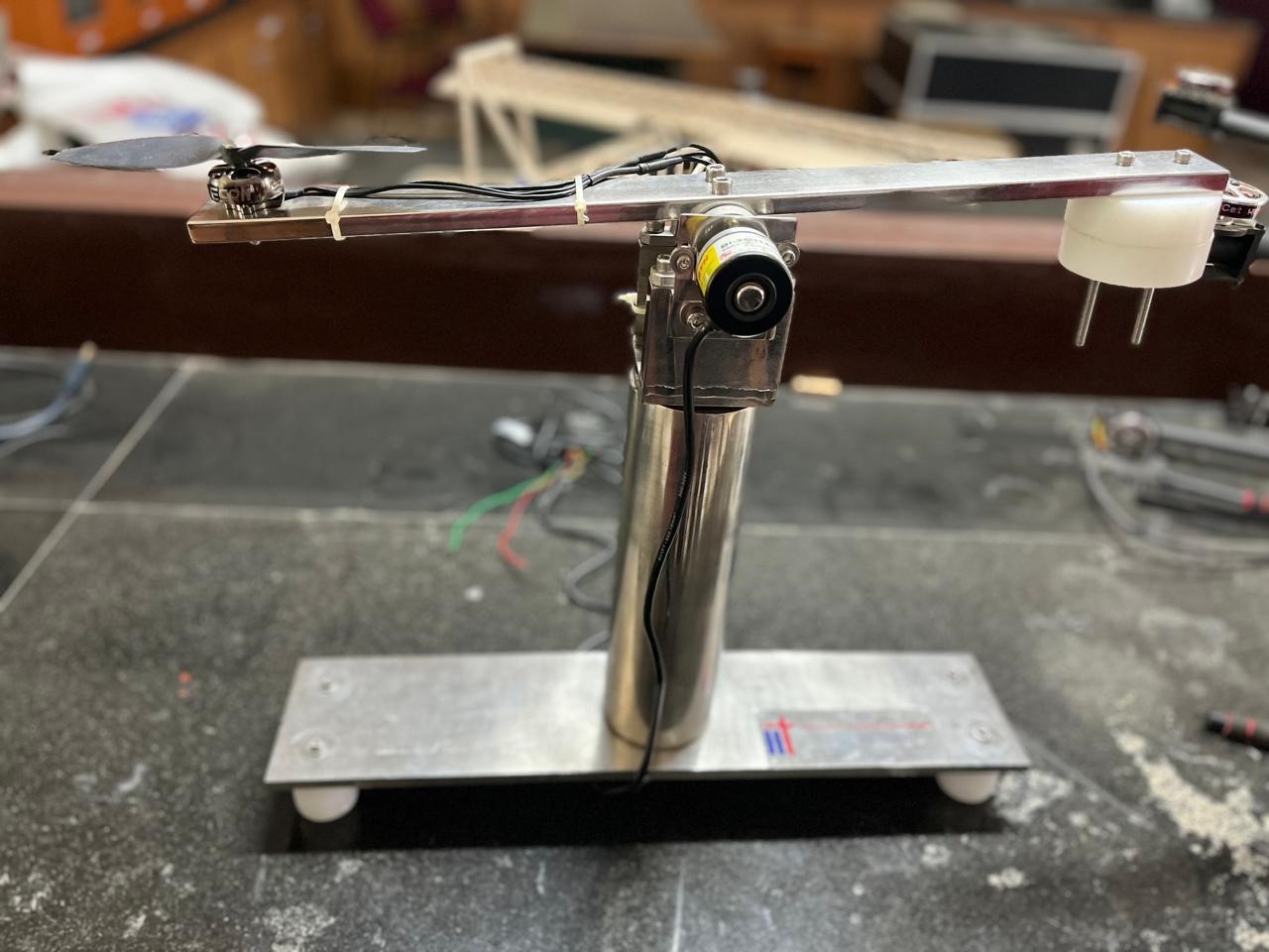
PID controller with Balancing Setup
In industrial control systems, a PID controller is a device that regulates the temperature, flow, pressure, speed, and other process variables. The most accurate and reliable controllers for these applications are proportional integral derivative (PID) controllers, which employ a control-loop feedback mechanism to maintain the desired level of process variables. PID control is a widely used method for guiding a system towards a desired location or level. It is utilized in various chemical and scientific processes as well as in automation and control systems to regulate rotor speeds. PID control employs closed-loop control feedback to maintain the actual output of a process that is as close to the target or setpoint output as possible. A PID controller primarily regulates the speed of the drone rotor in a speed control system. It receives input from an accelerometer/gyro sensor and compares the actual speed to the setpoint or the desired control speed. The control element receives output from the PID controller.
DRONE FABRICATION
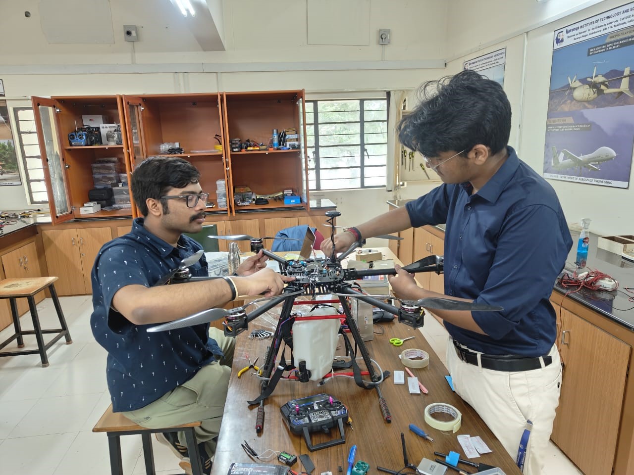
Drone Assembly
The Drone Fabrication and Assembly facility in the UAV lab is a cornerstone for aerospace engineering students, offering a hands-on environment for building and assembling UAVs. This facility is equipped with advanced tools and machinery for cutting, shaping, and joining various materials used in drone construction. Students learn to fabricate individual components and integrate them into fully functional drones, gaining practical skills in electronics, mechanics, and aerodynamics. The facility supports comprehensive training in the entire lifecycle of UAV development, from initial design and prototyping to final assembly and testing, preparing students for real-world challenges in drone engineering and innovation.
SUBSONIC WIND TUNNEL
The subsonic wind tunnel features a test section with dimensions of 600 mm by 600 mm by 4000 mm, designed to achieve a maximum velocity of 45 m/s. With a contraction ratio of 9:1, the tunnel efficiently streamlines airflow, minimizing turbulence and enhancing flow uniformity. It is powered by a motor with a maximum output of 22 kW and can reach up to 1500 rpm. This wind tunnel is ideal for various aerodynamic testing and educational purposes, providing precise control of airflow for accurate experimentation in areas such as lift calculation, drag reduction, airflow visualization, and aerodynamic research.
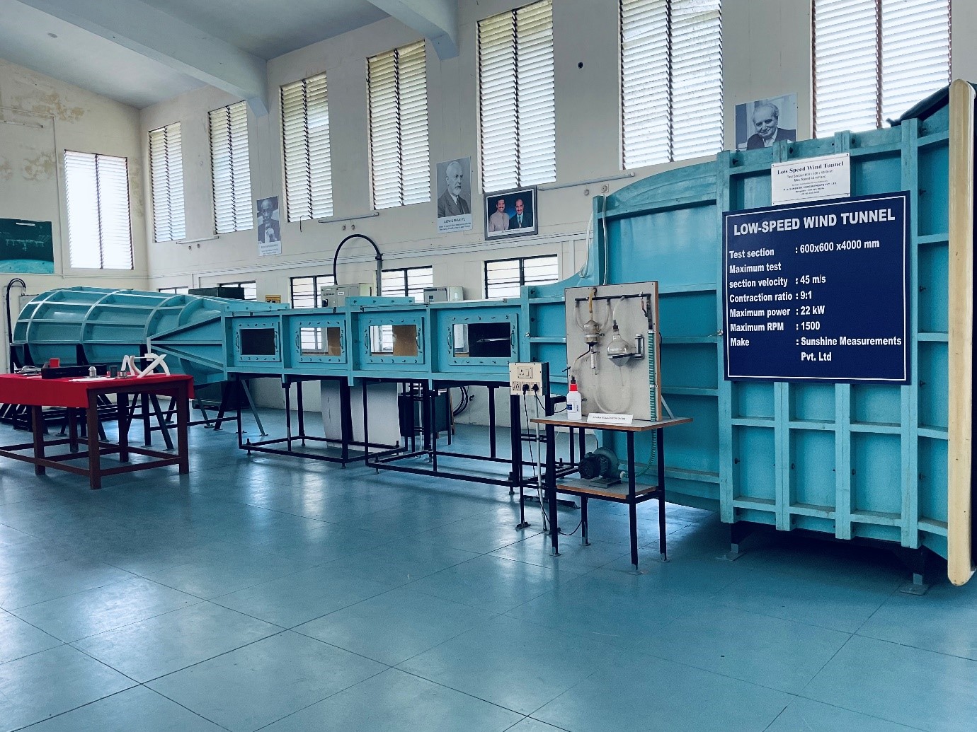
Subsonic wind tunnel setup
Specifications:
- Test section 600x600 mm
- Length of the test section 4 meters
- Maximum test section velocity 45 m/s
- Contraction ratio 9:1
- Maximum power 22KW
- Maximum RPM:1500
- Diameter of the Propeller blade: 1.3m
- Turbulence level: Below 2%
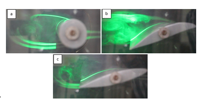
Flow visualization in Subsonic wind tunnel: Flow past a) cylinder, b) cambered aerofoil and c) symmetric aerofoil
SUPERSONIC WIND TUNNEL
The supersonic wind tunnel has a test section measuring 100 mm by 100 mm, capable of achieving Mach numbers from 1.5 to 3.5. It operates with a maximum stagnation pressure of 10 bar and allows for test durations of up to 20 seconds. The storage tank, with a volume of 14.14 cubic meters, can be pressurised to a maximum of 20 bar using two 20 HP compressors. This wind tunnel is designed for high-speed aerodynamic testing, enabling precise studies of supersonic flow behaviour and shock waves over various test specimens.
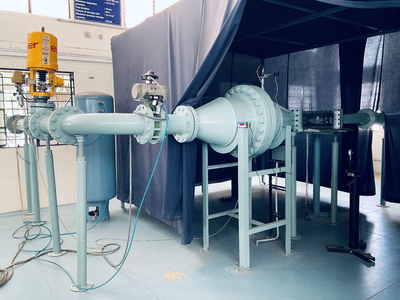
Supersonic wind tunnel setup
Specifications:
- Test section dimension 100X100 mm
- Range of Mach No:1.5 to 3.5
- Maximum Stagnation pressure: 10 bars
- Test duration: 20 sec. nominal
- Pressure measurement :16 port pressure scanner
- Volume of Pressure tank:14.14 m3
- Maximum Pressure storage capacity: 20 bars
- 20 hp Compressors-with air coolers and dryers
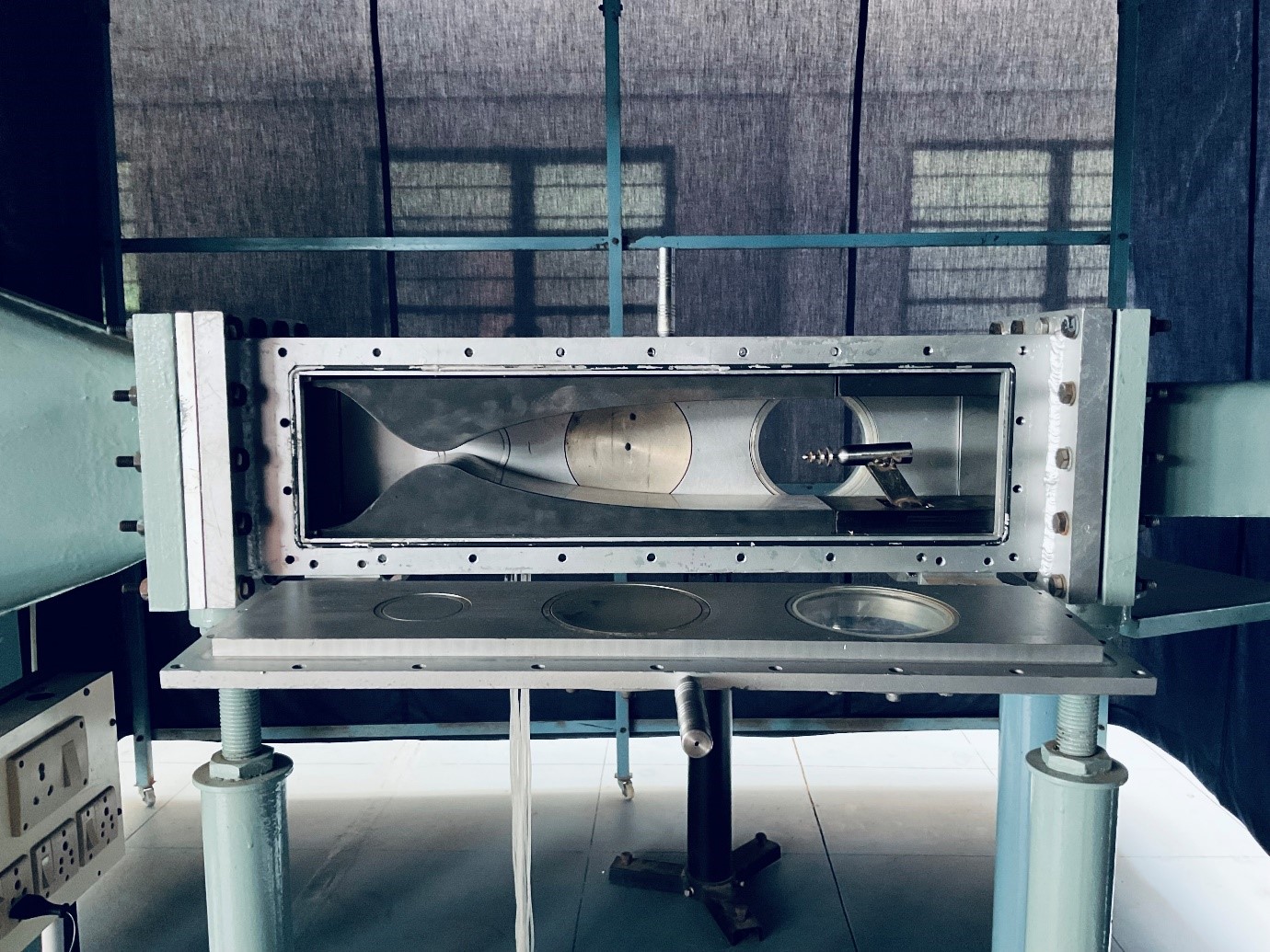
Supersonic wind tunnel test section
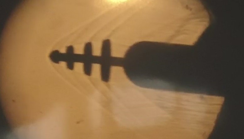
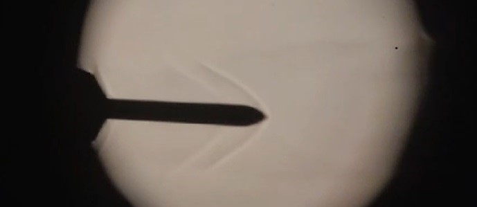
Flow visualization using Schlieren technique: Flow past Nose Spike
OPEN JET FACILITY
The blow-down type open jet facility is designed to reach a maximum Mach number of 2.5, making it ideal for high-speed aerodynamic testing. It can achieve a maximum stagnation pressure of 10 bar, providing robust testing conditions. The facility allows for a test duration of up to 100 seconds, offering sufficient time for detailed analysis of supersonic flow characteristics. This setup is particularly suited for studying the behavior of objects in high-speed airflows, shockwave interactions, and other supersonic phenomena.
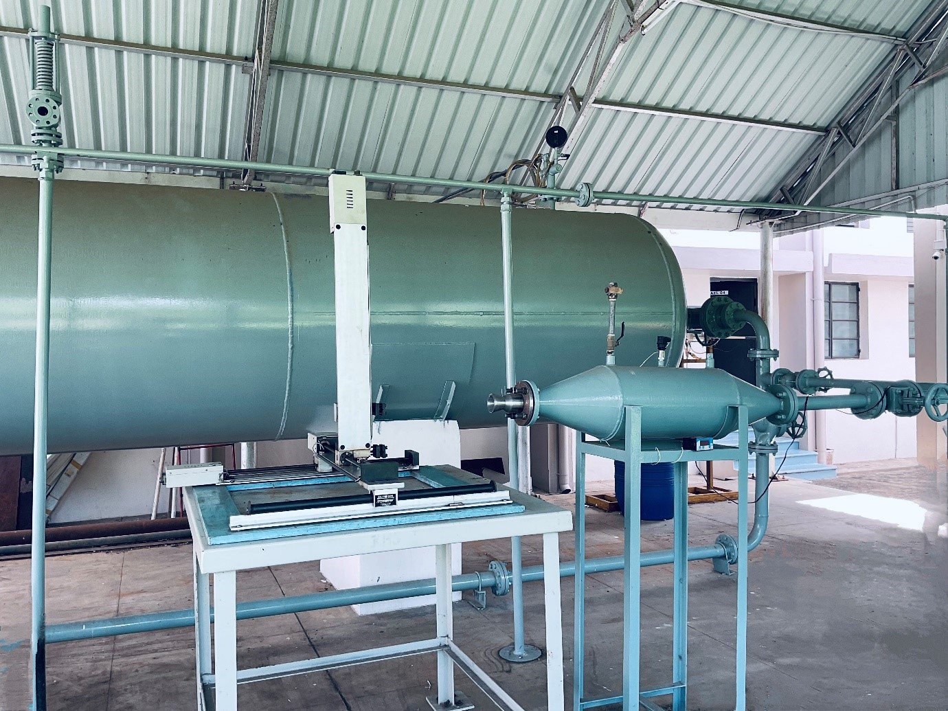
Open Jet facility
Flow visualization using Schlieren technique: Flow past missile fin.
Specifications:
- Blow down type
- Maximum Mach No:2.5
- Maximum Stagnation pressure: 10 bars
- Test duration: 100 sec. nominal
- Pressure measurement :16 port pressure scanner
- Volume of Pressure tank:14.14 m3
- Maximum Pressure storage capacity: 20 bars
- 20 hp Compressors-with air coolers and dryers
- Nozzle exit diameter=25 mm (max.)
OPEN WIND TUNNEL
The open wind tunnel, measuring 5 meters in length, features a tunnel diameter of 1 meter and achieves a maximum velocity of 12 m/s. It is designed to test the performance of wind turbine blades effectively. The power output is obtained using a 375-watt DC generator with a rated RPM of 500. This setup is ideal for optimizing blade designs, enhancing energy capture, and ensuring reliable performance in varying wind conditions, contributing to the development of more efficient and durable wind turbines.
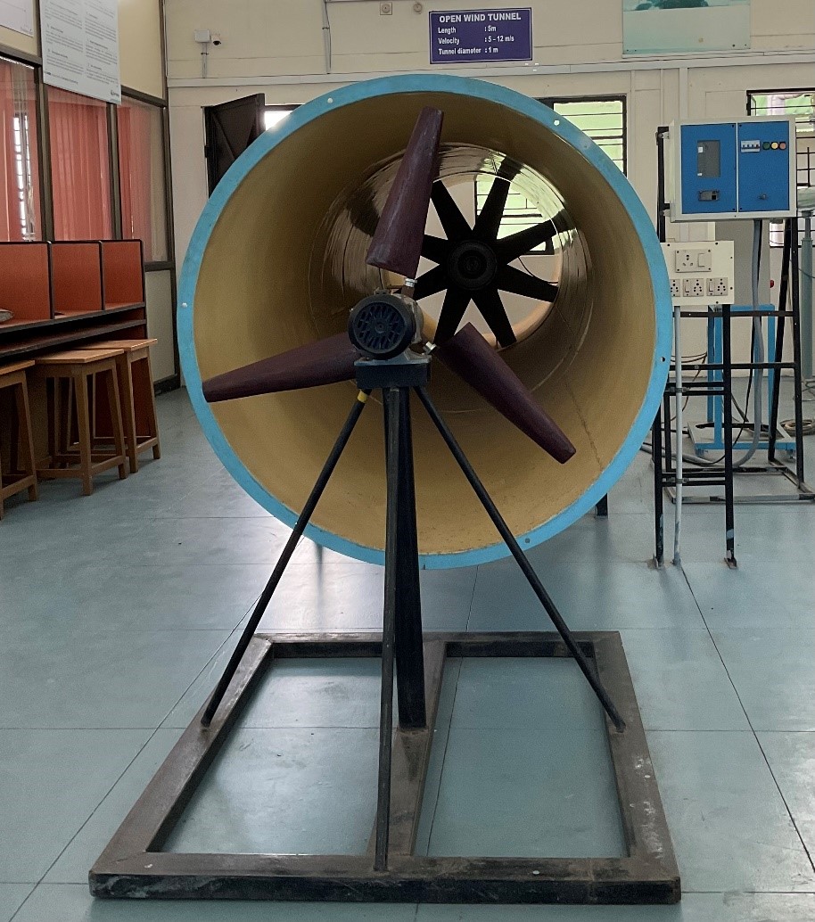
Open wind tunnel
Specifications:
- Tunel diameter: 1 meter
- Length of the tunnel: 5 meters
- Maximum velocity: 12 m/s
- DC Generator: 375W
- Maximum RPM: 500
CESSNA 152
The Cessna 152 is an American two-seat, fixed tricycle gear, general aviation airplane, used primarily for flight training and personal use.
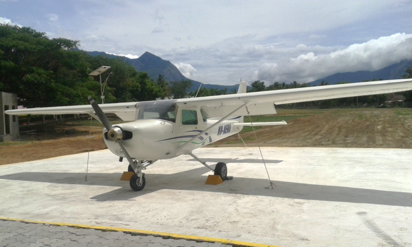
Using a Cessna 152 in an aerospace engineering program allows students to study flight mechanics and aerodynamics through practical demonstrations and data collection. It offers hands-on experience with aircraft systems and maintenance, enhancing their technical skills. The aircraft can be used for performance testing and modifications, providing a platform for research and innovation projects. Students can also gain first-hand piloting experience and learn safety and emergency procedures. Integrating the Cessna 152 into coursework and interdisciplinary projects enriches the educational experience by linking theory with real-world applications
General characteristics:
| Specification | Description |
| Model | CESSNA - 152 |
| Capacity | 2 seater |
| Wingspan | 33 ft 4 in (10.2 m) |
| Length | 24 ft 1 in (7.3 m) |
| Height | 8 ft 6 in (2.6 m) |
| Wing area | 160 ft² (14.9 m²) |
| Empty Weight | 1,081 lb (490 kg) |
| Max take-off Wt. | 1,670 lb (757 kg) |
| Max Range | 414nm (766km) |
| Service Ceiling | 14700ft (4480m) |
| Configuration | High Wing Vertical Tail |
| Engine Model | 1 x Lycoming 0235-L2C |
| Cylinder type | Horizontally Opposed |
| Cooling system | Air Cooled |
| Propeller model | MCCUELEY |
| Fuel | 100LL |
| Fuel Tank Capacity | 24.5 gallons (92.75 litres) |
AVIONICS LABORATORY
The Avionics lab in the department of Aerospace Engineering is equipped with
Communication protocol of MIL-STD-1553B data bus and ARINC-429 data bus wherein students are given the provision to practically demonstrate the same using lab view Software.
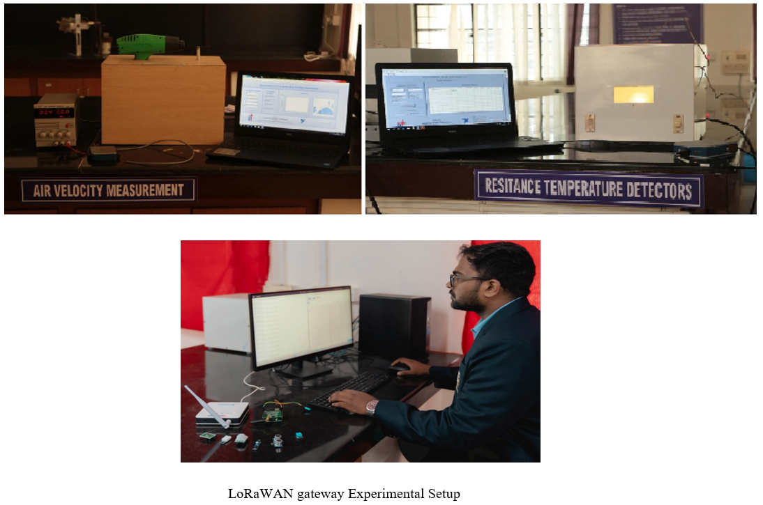
Experiments are carried on for measuring various avionic parameters like temperature, Acceleration, position, Velocity using thermocouple, Accelerometer, GPS and Anemometer.
Performance study of simulation using MATLAB on Van Guard Missile System and Autopilot Control systems and also carried out.
Measurement of temperature and humidity using LoRaWAN gateway is carried out wherein the LPS8 is an open source LoRaWAN Gateway. It bridges LoRa wireless network to an IP network via WiFi, Ethernet.
The lab is equipped with RTOS facility wherein students receive hands on experience to execute the written RTOS API based exercise on APPCOE IDE and to develop RTOS based application and interface with Raspberry Pi and Arduino from APPCOE.
Thus, the students are blended with project-based learning in a class room environment.